- Full PBN solution for corrosive materials like Te, Sb, Se, As, Mg
- DN40CF ( O.D. 2.75" ) mounting flange c ompatible with all MBE systems
- Thermal cracking up to 1300°C
- 35 cm3 or 130 cm3 PBN crucible
- Excellent thermal isolation between low temperature reservoir and hot cracking zone
- Integrated water cooling for cracker stage
- Integrated rotary shutter Datasheet
Introduction
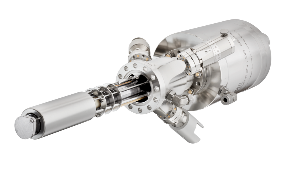
The Thermal Cracker Cell TCC is an effusion cell equipped with a cracker stage with integrated water cooling shroud on its space-saving DN40CF ( O.D. 2.75") flange. The cell features a crucible size of 35 cm 3 or 130 cm3 which is sufficient for most R&D applications.


The TCC is designed for evaporation of materials at operation temperatures from 100°C to 650°C with an additional cracker stage on the end of the injector tube that provides temperatures up to 1300°C.
The crucible is heated by a tantalum wire heater. The standard crucible material suitable for most evaporants is PBN.
The shielding of the crucible is reduced to optimize the cell for low temperature operation. That way a good flux control for high vapor pressure materials is possible without using an additional valve.
The crucible and cracker zones are shrouded by water cooling therefore the thermal load on the chamber is neglectable.
This is realized by excellent thermal insulation between the low temperature reservoir and the hot cracking zone.
The figure “TCC time-temperature diagramm for heating of the cracker only” shows the temperature response of tube and crucible in case of heating the cracker only. The aim of the TCC is to reduce the thermal crosstalk of the cracker and the reservoir.
The temperature is measured by thermocouples on application critical positions: within the cracker zone, the tube and at the bottom of the crucible.
Even at cracker temperatures around maximum temperature of 1300°C the temperatures of tube and crucible stay unaffected to a large extend.
Application
A source concept like this is used for high vapor pressure materials, which form atom clusters. Typical evaporation elements are As, Se, Sb, Te, Mg.
Technical Characteristics
| Mounting Flange | DN40CF (O.D. 2.75") |
| In‑vacuum dimensions | L=220 mm or 287 mm TL=240 mm or 307 mm (with shutter) |
| Airside dimensions | AL=405 mm AR=106 mm |
| Filament | Reservoir: Ta wire filament ,Tube: Ta wire filament, Cracker: Ta wire filament |
| Thermocouple, Temperature sensor (other types on request) | Reservoir: Type K Tube: Type C Cracker: Type C |
| Operating pressure | 1×10-11 mbar - 1×10⁻⁵ mbar |
| Operating temperature | Reservoir: 100°C – 650°C ,Tube: 200°C – 800°C, Cracker: 300°C – 1200°C |
| Outgassing temperature | Reservoir: Up to 700°C ,Tube: Up to 850°C, Cracker: Up to 1300°C |
| Bakeout temperature | 200°C |
| Cooling / water cooling | Reservoir: Integrated water cooling shroud Tube: None Cracker: Integrated water cooling shroud |
| Cooling water flow | 30-90 l/h |
| Crucibles | PBN 130cm³ |
| Options | integrated rotary shutter (S) |
| Shutter opening angle | 90° ccw |
| Weight | 13 kg |
| Tube material | PBN |
| Cracking insert material | PBN |
Technical Data
For general information on CF mounting flanges see Flange, Gasket and Tube Dimensions .| Product | Flange [CF] | Nominal capacity [cm³] | Lip diameter [mm] | Cooling | Shutter | UHV dimensions [mm] specify L with order | |
|---|---|---|---|---|---|---|---|
| TCC | 40 | 35 | 37 | K | S | LxxxD36 | |
| TCC | 40 | 130 | 54 | K | S | LxxxD36 | |
Technical specifications are subject to change without notice.


