- H 2 dissociation typically 80-98%, depending on operation conditions
- Atomic hydrogen flux density up to 1*10 16 /(cm 2 s)
- No high-energy particles and ions
- Low power consumption (P < 200 W)
- Integrated water cooling, low thermal load on other experimental equipment
- Integrated shutter optional
- Additional customized aperture and leak valve available Datasheet
Introduction
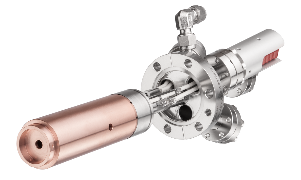
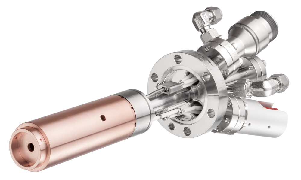
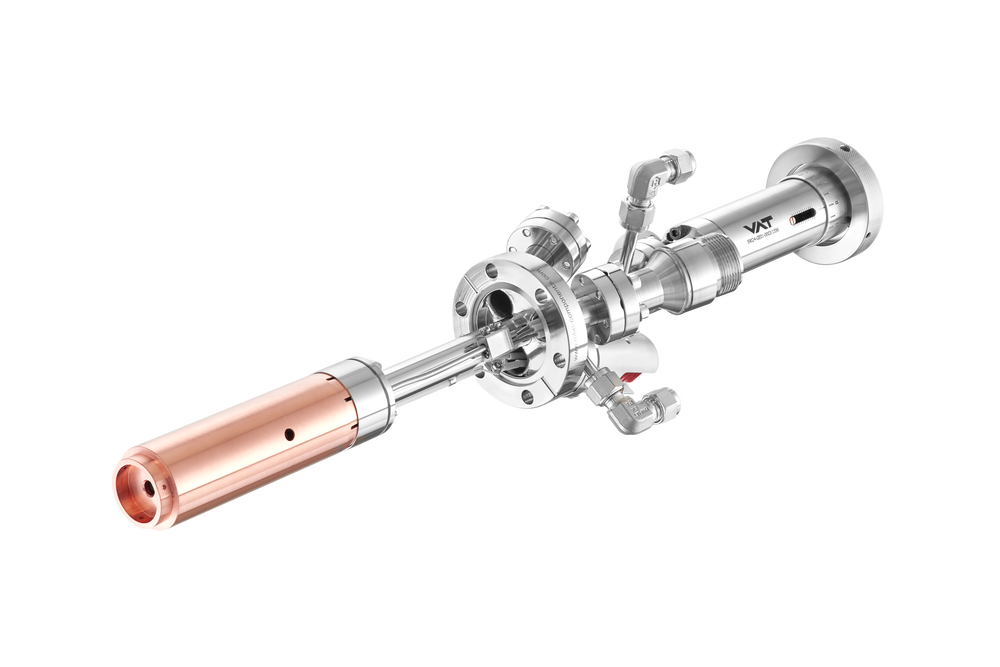
The Hydrogen Atom Beam Source HABS is a thermal gas cracker that
produces an absolutely ion-free hydrogen gas beam, thus avoiding ion
induced damage to the substrate. In comparison to hydrogen sources based
on electron bombardment heating the HABS is heated by a DC operated
tungsten filament.
The source was developed and completely characterized by Dr. Karl G.
Tschersich, Institute of Bio- and Nanosystems (formerly Institute of
Thin Films and Interfaces) at Juelich Research Centre. Dr. Eberl
MBE-Komponenten produces and markets the HABS under the license of
Forschungszentrum Jülich GmbH (
www.fz-juelich.de) .


Usually the gas flow is regulated by a UHV leak valve or a mass flow
controller which allow switching on and off the atom flux within several
seconds. Short exposures can be terminated by a shutter (option S) which
attenuates the hydrogen atom flux down to the detection level.
Hydrogen atoms passing the sample and hitting the chamber walls can
induce reactions detrimental to the experiment. A customized aperture
plate is available which limits the solid angle of hydrogen atom
emission. Outside this angle no beam atoms could be detected by the
QMA.
So far the HABS has been only operated with hydrogen. The source could perhaps be used as well as a radical beam source by decomposing other molecules at temperatures up to 2000°C. Please inquire for your special application. For production of atomic oxygen please refer to our source OBS .
A basic description of the cell design as well as some results from the characterization were published in the papers, listed section References / List of Publications .
General properties of the HABS which are derived from the cell characterization in the above mentioned reference [3] are shown and discussed in the following.
The intensity of the source can be controlled by the flow rate of hydrogen and the heating power. The heating power determines the temperature of the capillary. With respect to control of these operational parameters we suggest different procedures for high and low intensity runs.
In case of high intensity runs the gas feed is preferably maintained by means of a mass flow controller installed in the gas feed line. Mass flow controllers do not require hands-on control of the gas feed thus making unattended long-term runs feasible. They are appropriate for higher gas flow rates. When the flow rate has been preset the intensity can be adjusted by the heating power.
Figure 1 shows the on-axis (peak) H-atom flux density as a function of the heating power for different feeding gas flows. The sample is positioned 6 cm in front of the capillary. The flux density can reach as much as some monolayers per second.
Low intensities result from low gas flow rate and/or low heating power. Low flow rates can be adjusted by means of a leak valve installed in the gas feed line. In this configuration the heating power can be preset and the atom beam intensity varied by manipulating the leak valve. By measuring the pressure where the gas line is connected to the source, the flow rate can be evaluated as the product of this pressure and the flow conductance of the source. The conductance has been measured and is 6.1 cm 3 /s when the capillary is hot.
Figure 2 shows the on-axis hydrogen atom flux density at the same sample as above, again distance 6cm, as a function of the gas feed flow rate. (1 mbar l/s corresponds to 54.9 sccm). Flux densities as low as a tenth of a monolayer per second were measured.
The degree of dissociation depends on several factors, e.g. the temperature of the capillary. Measurements with a pyrometer showed a temperature of the capillary orifice ranging from 1570°C @ 80 W heater power up to 2030°C @ 187 W. (Due to its position at the bottom of the heater the TC of the HABS shows temperatures 100-200°C lower than the true capillary temperature.)
Figure 3 shows a contour plot of the parameter field. The flux density is plotted as a function of both the heating power and gas flow rate into a single diagram. The flux density increases with increasing gas flow rate as well as with increasing heater power as a result of the increased degree of dissociation.
Development and characterization of the HABS
Several years ago, in the former Institute of Surface Research and Vacuum Physics, Dr. Tschersich et.al. started to develop a hydrogen atom beam source intended to support thin film deposition by molecular beams. The primary goals were:
- atom energy limited to thermal energy,
- high beam intensity at low gas load of the vacuum chamber,
- evaluation of the beam intensity.
To meet these requirements the group around Dr. Tschersich adopted the hot capillary design. Up to this point, the hot capillary had been heated by electron impact which involved high voltage. Although deflection plates were applied the group could not strictly avoid high-energy electrons accompanying the hydrogen atoms. Based on the new understanding of the source the group decided to switch from electron bombardment heating to the somewhat less powerful but technically much simpler resistive heating and developed the present version of the source. This design meets the first requirement due to pure thermal dissociation of the gas passing through the hot capillary. The second goal is approached by the beam formation due to molecular flow in the capillary. The molecular flow was reconsidered and an analytical expression found describing the angular distribution of the emitted hydrogen atoms, see reference [1] above. This work made it feasible to finally determine the intensity of the source from quadrupole mass analyzer measurements, reference [2].
The group built up a new QMA apparatus improving the differential pumping, the signal-to-noise ratio of the H 1 and H 2 signals and the accessible polar angle range. In a separate set of measurements this apparatus was calibrated with respect to its absolute sensitivity for hydrogen atoms and molecules. The performance of the source presented here was determined by the calibrated QMA apparatus. The calibration of the QMA apparatus was performed as follows. Using a special source without any obstacles (like radiation shields) ahead of the capillary orifice the unperturbed angular distribution of the QMA signal of hydrogen atoms and molecules was measured. The following two figures show some of their results.
The experimental data covering the polar angle range from -30 to +30 degrees were fitted by analytical functions, which were extrapolated to 90 degrees and integrated to give the integral signal representing the total flux of hydrogen atoms and molecules into the hemisphere ahead of the capillary orifice. Measuring these fluxes at different capillary temperatures, i.e. at different degrees of dissociation, but at constant mass flow rate, enables the QMA sensitivity for hydrogen atoms and molecules to be determined from the mass balance.

Application
Typical applications for the HABS are low temperature surface cleaning, promotion of 2D growth of GaAs, enhancing of GaN growth rate or H surfactant growth in Si or GaAs MBE. Several publilcations to these applications are listed in section References / List of Publications .
Low Temperature Surface Cleaning of InP and GaAs
In MBE the cleaning of substrate surfaces is very important to reach
high quality epitaxial films. GaAs or InP substrate wafers can be
cleaned while being irradiated with atomic H. Carbon contamination is
removed at temperatures as low as about 200°C and oxygen at temperatures
of about 400°C.
Si Substrate Preparation / GaAs on Si
Atomic hydrogen is used for in-situ cleaning of Si substrates, leading
to significant reductions in surface contamination. Atomic hydrogen
irradiation has also been used during growth of GaAs on Si substrates to
achieve lower defect densities.
Promotion of 2D Growth of GaAs
Improved properties of MBE grown GaAs is reported after atomic hydrogen
enhanced growth, compared with standard grown GaAs.
Selective Epitaxial Growth in MBE and GS MBE
Another feature of atomic hydrogen enhanced MBE growth is selective
epitaxial growth. This technique allows local selective deposition of
MBE related materials onto a prepared substrate.
Gas Injection System

For optimized performance, we offer a complete gas injection system for
atomic hydrogen. The gas injection system is completely assembled and
only an H2 gas cylinder is required to start operation. A
simple turbo molecular pump can be used to evacuate the H2
gas line. The H2 gas line and all-metal leak valve can be
baked to 180°C.
Alternatively, the gas injection system can be equipped with a mass flow
controller (MFC) plus an all-metal valve instead of an all-metal UHV
leak valve. A mass flow controller in the gas line is preferred when the
HABS is used primarily for high intensity, long term runs, where mass
flow controllers require less attention due to their automated operation
compared to the gas feed setup above.
There are many different mass flow controllers on the market. It is
recommended that the customer provide the MFC. The maximum system
bake-out temperature depends on the specification of the MFC used.
- fully UHV compatible
- H 2 gas cracking cell
- all-metal UHV leak valve / mass flow controller (MFC) plus all-metal valve for shut-off during MFC maintenance
- all-metal valve for gas feed evacuation
- H 2 gas purifier
- flexible UHV tube 1m max. length
- bakeable system
- H 2 bottle and stainless steel
gas
pressure reducing regulator (not included)
| Filament type | tungsten filament |
| Gas line | filament heated W capillary |
| Thermocouple | W5%Re/W26%Re (type C) |
| Bakeout temperature | 250°C |
| Operating temperature | up to 2000ºC |
| Cooling | integrated water cooling |
| Options | integrated shutter ( S ) |
| Accessories | aperture plate, leak valve |
Dimensions

Specific data
For general information on CF mounting flanges see Flange and Gasketdimensions .
| Product | CF flange | Shutter* | UHV dimensions*** [mm] | max. electrical [W]/[A] | Power supply product code | |
|---|---|---|---|---|---|---|
| [mm] / [mm] | [W] / [A] | Product code | ||||
| HABS | 40 - | S - | LxxxD36 | 200/ 15 | PS 30-25 |
* rotary shutter possible on same flange *** specify UHV length L with order
Product code: e.g. HABS 40-S-L290D36 is a hydrogen atom beam source on DN40CF flange with integrated shutter; UHV-length 290 mm and in-vacuum diameter 36 mm.


