
Why MC-Simulation?
- It provides important information while saving time and money
MC-Simulation allows the optimization of
- source design
- source arrangement
- deposition chamber layout
It provides information about
- layer uniformity
- material efficiency
- layer composition
For single material deposition and co-evaporation For planar, patterned or textured substrates


Introduction
Monte Carlo simulation allows to calculate the angular flux distribution of various types of effusion cells with or without beam shaping inserts. It provides information on the resulting flow rate distribution, material composition on the substrate, and material efficiency, which allows to optimize the system design.
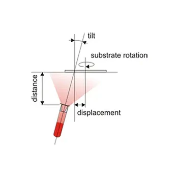
An example of a multible MBE system is shown in the figure above. Multiple radially arranged effusion sources are used to deposit materials onto a rotating substrate. The substrate is a semiconductor wafer in face-down position.
An example is shown in the figure on the right. It shows an effusion cell that allows evaporating material onto a rotating 3-inch wafer. The figure shows the calculated 2D flux density distribution for an effusion cell. The simulated window size is 100x100 mm². The substrate is the rotating 3-inch plate.
The normalized thickness profile derived from the 2D flux density map is shown above. In one case the effusion cell is equipped with a beam shaping insert. In the second case, where the effusion cell is without insert, the flux distribution is defined by the cylindrical crucible, which results in a strong drop of the thickness profile with increasing radius.
The example proves that beam shaping inserts significantly improve thickness homogeneity in cylindrical crucibles. However true peak performance requires a macro-level approach. By holistically optimizing the entire system geometry - including the crucible, beam shaper, chamber layout, and substrate arrangement - we achieve results that exceed the capabilities of only using inserts. Our OCTOPLUS MBE Systems leverage this comprehensive optimization to guarantee maximum material utilization and unmatched layer homogeneity.
We offer the deposition simulation for your MBE or PVD system as a service. For a specific simulation geometrical boundary conditions of the deposition setup are required.
Technical specifications are subject to change without notice.